Introduction to Fourier Optics
Fourier optics is a branch of optics that studies how optical systems process light by using the mathematical principles of Fourier transforms. It provides a framework for understanding how lenses, apertures, and optical instruments manipulate light waves and produce images. In essence, Fourier optics describes how spatial variations in light waves can be analyzed and transformed into frequency components.
The field emerged from the understanding that light behaves as a wave, and wave propagation phenomena such as diffraction and interference can be analyzed using Fourier analysis. When light passes through an aperture, lens, or other optical elements, its amplitude and phase distributions change. These changes can often be described mathematically using Fourier transforms, which convert spatial information into spatial frequency information.
Fourier optics is widely applied in many areas including image processing, microscopy, holography, optical communication, laser systems, astronomical imaging, and optical signal processing. It also forms the theoretical basis for many modern technologies such as digital holography, spatial filtering, and adaptive optics.
The key idea behind Fourier optics is that any complex optical wavefront can be decomposed into a superposition of plane waves with different spatial frequencies. Optical elements like lenses can perform Fourier transforms of optical fields, allowing the manipulation of these frequency components.
Understanding Fourier optics helps explain phenomena like diffraction patterns, resolution limits in imaging systems, and the functioning of optical instruments.
Historical Development of Fourier Optics


The concept of Fourier optics originates from the work of the French mathematician Joseph Fourier in the early nineteenth century. Fourier introduced the idea that any periodic function could be represented as a sum of sine and cosine waves, known as Fourier series. Later, this idea was generalized into the Fourier transform, which can represent non-periodic functions as continuous distributions of frequencies.
During the nineteenth century, scientists studying diffraction and interference realized that Fourier analysis could explain how light waves interact with apertures and obstacles. The German physicist Joseph von Fraunhofer made significant contributions by studying diffraction patterns produced by light passing through slits and gratings.
Later developments in wave optics showed that diffraction patterns observed in the far field correspond to the Fourier transform of the aperture function. This discovery provided a powerful connection between mathematical analysis and optical phenomena.
In the twentieth century, the development of lasers and coherent light sources greatly expanded the practical applications of Fourier optics. Researchers began using lenses to perform optical Fourier transforms, enabling real-time optical signal processing.
The invention of holography and advanced imaging techniques further strengthened the importance of Fourier optics. Today it is an essential component of modern photonics and optical engineering.
Mathematical Foundations of Fourier Optics


The mathematical foundation of Fourier optics is based on Fourier transforms and wave propagation equations.
In optics, light can be represented as a complex wave function that describes both amplitude and phase. If the optical field distribution at a plane is represented by a function ( U(x,y) ), its Fourier transform describes the distribution of spatial frequencies.
The two-dimensional Fourier transform is written as
[
F(f_x,f_y)=\int\int U(x,y)e^{-i2\pi(f_xx+f_yy)}dxdy
]
Here:
- (U(x,y)) represents the optical field in spatial coordinates
- (f_x, f_y) represent spatial frequency components
- (F(f_x,f_y)) represents the Fourier transform of the optical field
Spatial frequency describes how rapidly the light intensity changes across space. High spatial frequencies correspond to fine details in an image, while low spatial frequencies correspond to coarse structures.
In imaging systems, lenses perform Fourier transforms of optical fields. When a coherent light beam passes through a lens, the field distribution at the focal plane is proportional to the Fourier transform of the input field distribution.
This property allows optical systems to manipulate spatial frequency components using filters placed at the Fourier plane.
Diffraction and Fourier Optics


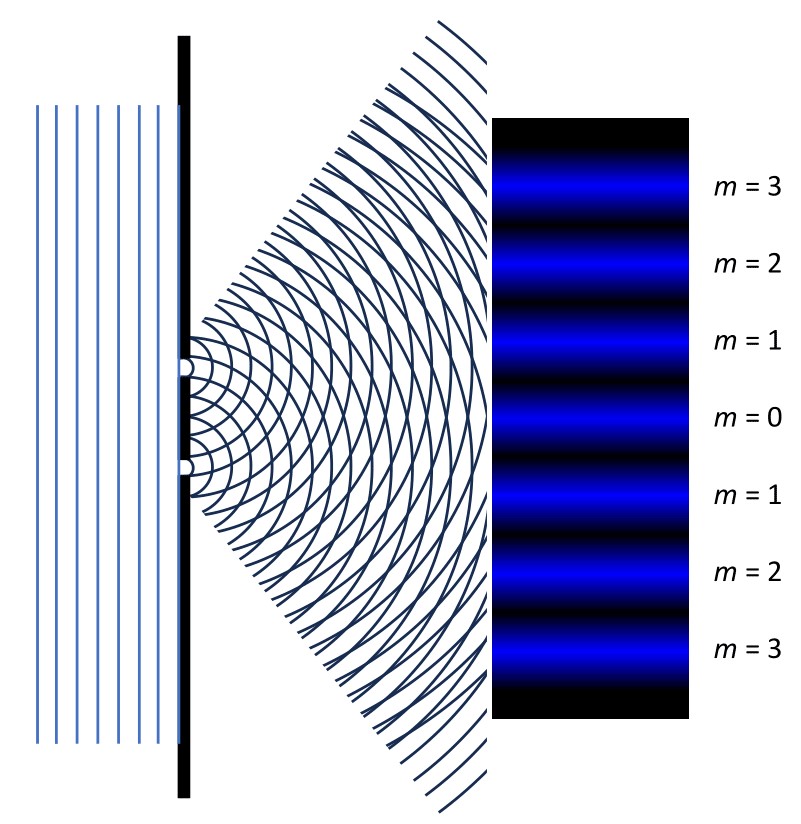
Diffraction is one of the most important phenomena explained using Fourier optics. It occurs when light waves encounter an obstacle or aperture and spread out.
Fourier optics shows that the diffraction pattern observed in the far field is the Fourier transform of the aperture function.
For example:
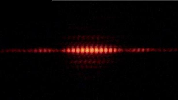
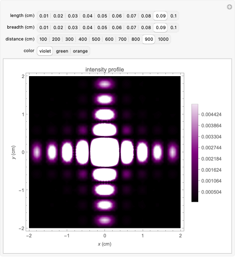
If a plane wave passes through a single slit, the aperture function is rectangular. The Fourier transform of a rectangular function is a sinc function. Therefore, the diffraction pattern consists of a central maximum with decreasing side lobes.
For a circular aperture, the diffraction pattern forms an Airy disk. This pattern determines the fundamental resolution limit of optical instruments such as telescopes and microscopes.
Mathematically, diffraction patterns can be predicted using the Fresnel and Fraunhofer approximations.
Fraunhofer diffraction occurs when the observation screen is very far from the aperture or when a lens is used to focus the pattern at its focal plane. In this case, the diffraction pattern corresponds directly to the Fourier transform of the aperture.
Fresnel diffraction occurs when the observation distance is finite. It requires more complex calculations but can still be analyzed using Fourier methods.
Optical Fourier Transform Using Lenses


One of the most powerful ideas in Fourier optics is that lenses can perform Fourier transforms of optical wavefronts.
Consider a coherent light beam passing through an object and then through a converging lens. The lens focuses the light such that the field distribution at the focal plane represents the Fourier transform of the object’s transmission function.
This principle forms the basis of the 4f optical system.
The 4f system consists of:
Object plane → Lens → Fourier plane → Lens → Image plane
The first lens produces the Fourier transform of the object at its focal plane. This plane is called the Fourier plane.
If a filter is placed at the Fourier plane, it can selectively block or modify certain spatial frequencies. The second lens then performs an inverse Fourier transform to reconstruct the modified image.
This method allows optical filtering operations such as:
- Low-pass filtering
- High-pass filtering
- Edge enhancement
- Image sharpening
Because optical processing occurs at the speed of light, such systems can process images extremely quickly.
Spatial Filtering in Fourier Optics
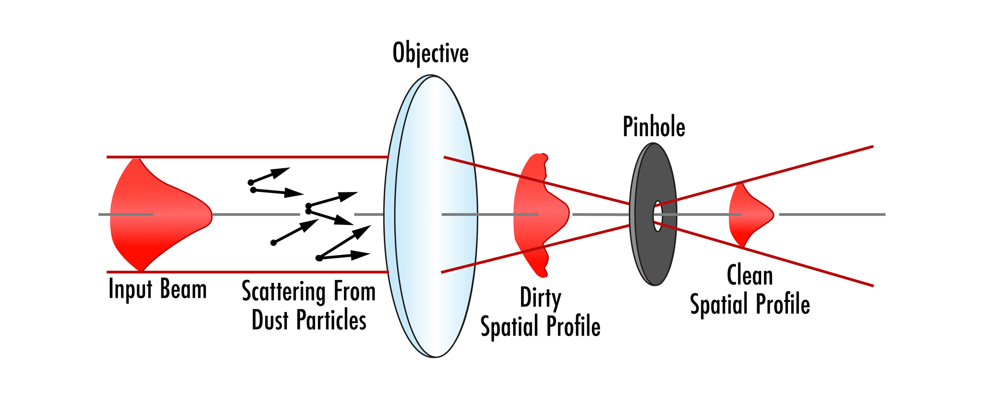
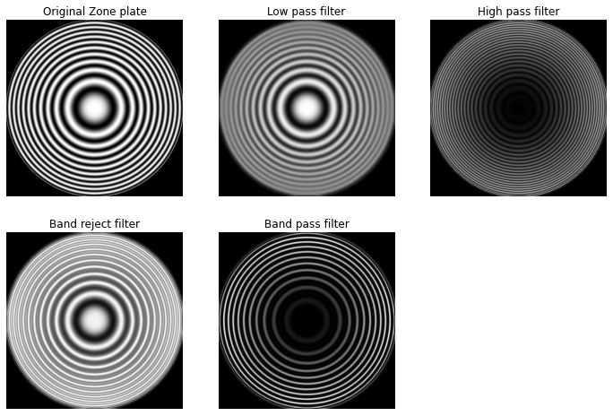

Spatial filtering is a technique used to manipulate the spatial frequency components of an optical signal.
When the Fourier transform of an image is formed at the Fourier plane of a lens system, each point in that plane corresponds to a specific spatial frequency.
By placing masks or filters at that plane, certain frequencies can be suppressed or enhanced.
Low-pass filters allow low spatial frequencies to pass while blocking high frequencies. This produces a blurred image because fine details are removed.
High-pass filters block low frequencies and allow high frequencies to pass. This enhances edges and fine details.
Band-pass filters allow only a certain range of spatial frequencies to pass.
Spatial filtering is widely used in:
- Image enhancement
- Pattern recognition
- Optical computing
- Laser beam shaping
It demonstrates how optical systems can perform mathematical operations on images.
Optical Transfer Function and Imaging Systems


In Fourier optics, imaging systems are often analyzed using the Optical Transfer Function (OTF).
The OTF describes how different spatial frequencies are transmitted through an optical system.
It is the Fourier transform of the Point Spread Function (PSF).
The PSF represents the response of an imaging system to a point source of light.
If a point source is imaged perfectly, it would produce a single point. However, due to diffraction and aberrations, the image spreads out into a small pattern.
The OTF describes how the contrast of spatial frequencies is affected by the system.
A related function called the Modulation Transfer Function (MTF) represents the magnitude of the OTF and indicates how well the system preserves contrast at different spatial frequencies.
High-quality optical systems have high MTF values across a wide range of spatial frequencies.
These functions are important in designing cameras, microscopes, telescopes, and imaging sensors.
Applications of Fourier Optics


Fourier optics has numerous applications in science and technology.
Optical Imaging
Fourier optics helps analyze resolution limits and image formation in optical systems.
Holography
Holography records both amplitude and phase information of light waves. Fourier analysis helps reconstruct three-dimensional images.
Microscopy
Advanced microscopy techniques such as phase-contrast and confocal microscopy rely on Fourier optical principles.
Optical Signal Processing
Optical systems can perform mathematical operations such as convolution and correlation using Fourier transforms.
Astronomy
Telescopes use Fourier optics to analyze diffraction patterns and improve imaging resolution.
Laser Systems
Laser beam shaping and optical resonator design rely heavily on Fourier optical analysis.
Fourier Optics in Modern Technology


Modern photonics technologies rely heavily on Fourier optics.
Digital holography uses Fourier transforms to reconstruct images from interference patterns.
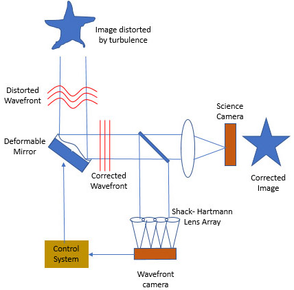
Adaptive optics systems use wavefront sensors and deformable mirrors to correct distortions caused by atmospheric turbulence.
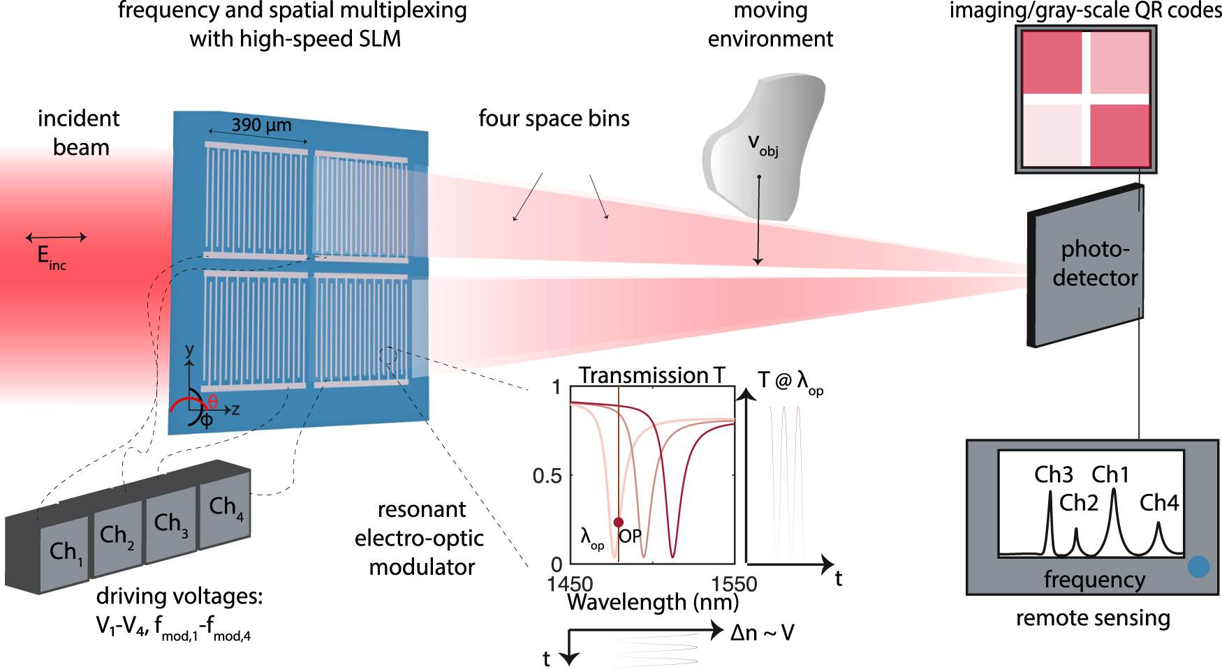
Spatial light modulators allow dynamic control of optical wavefronts, enabling programmable optical Fourier processing.
Optical computing systems use Fourier optical techniques for pattern recognition and parallel processing.
These technologies demonstrate the continuing importance of Fourier optics in modern science.
Advantages and Limitations of Fourier Optics
Advantages
- Provides powerful mathematical framework for wave propagation
- Enables real-time optical signal processing
- Useful for analyzing imaging systems
- Enables high-speed image processing
- Essential for modern photonics technologies
Limitations
- Requires coherent light for many applications
- Sensitive to noise and aberrations
- Complex mathematical analysis
- Some approximations are valid only under specific conditions
Despite these limitations, Fourier optics remains one of the most important tools in optical physics and engineering.
Conclusion
Fourier optics provides a powerful way to understand how optical systems manipulate light waves. By using Fourier transforms, complex optical phenomena such as diffraction, image formation, and spatial filtering can be analyzed mathematically.
The concept that lenses can perform Fourier transforms of optical fields allows optical systems to process images and signals in ways similar to electronic or digital systems.
From microscopes and telescopes to holography and optical computing, Fourier optics plays a crucial role in modern science and technology.
As optical technologies continue to advance, Fourier optics will remain an essential field for understanding and designing sophisticated photonic systems.