


Introduction
A transmission line is a specialized electrical structure designed to carry electrical signals or electromagnetic energy from one point to another with minimal loss and distortion. Transmission lines are essential components in electrical engineering, telecommunications, radio-frequency systems, and microwave technologies.
Unlike ordinary wires used for low-frequency electrical power transmission, transmission lines are specifically designed to handle high-frequency signals. At high frequencies, electrical signals behave as electromagnetic waves rather than simple current flow, making it necessary to analyze transmission lines using wave theory.
Transmission lines are widely used in various applications, including:
- Radio communication systems
- Television broadcasting networks
- Computer networks
- Microwave engineering
- Power distribution systems
The theory of transmission lines involves understanding how voltage and current vary along the line, how electromagnetic waves propagate through conductors, and how impedance affects signal transmission.
Transmission line theory is based on Maxwell’s equations, which describe the behavior of electromagnetic fields.
Basic Concept of Transmission Lines
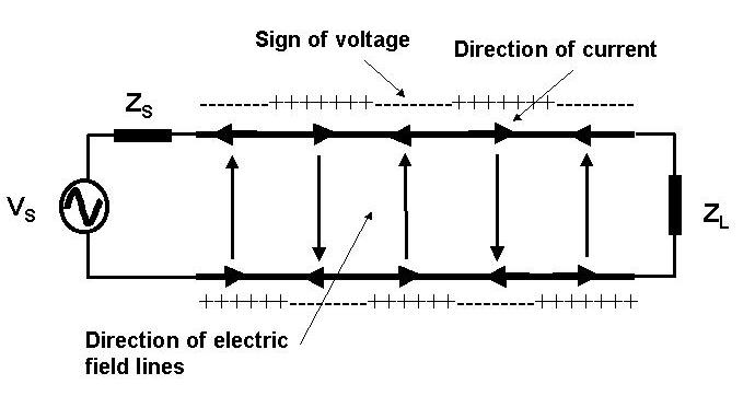

A transmission line consists of two or more conductors that guide electrical signals between a source and a load.
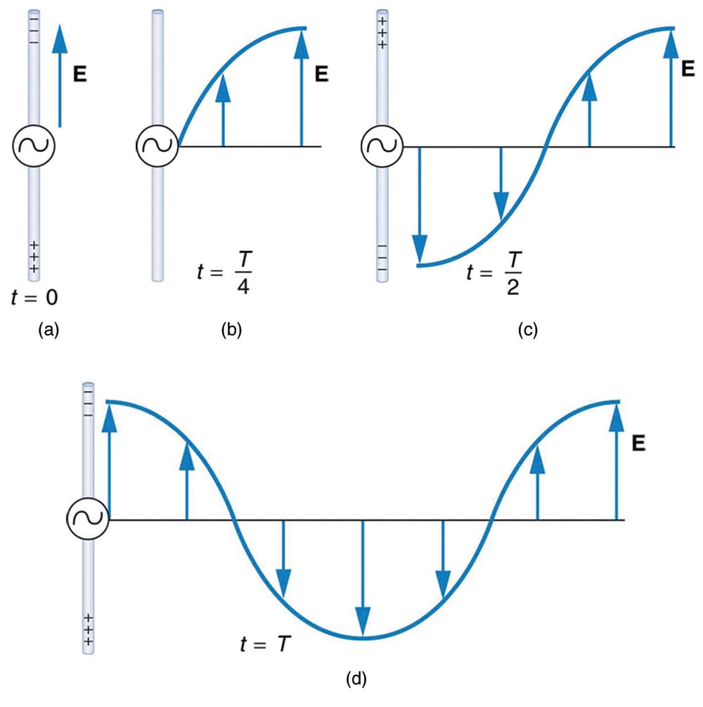
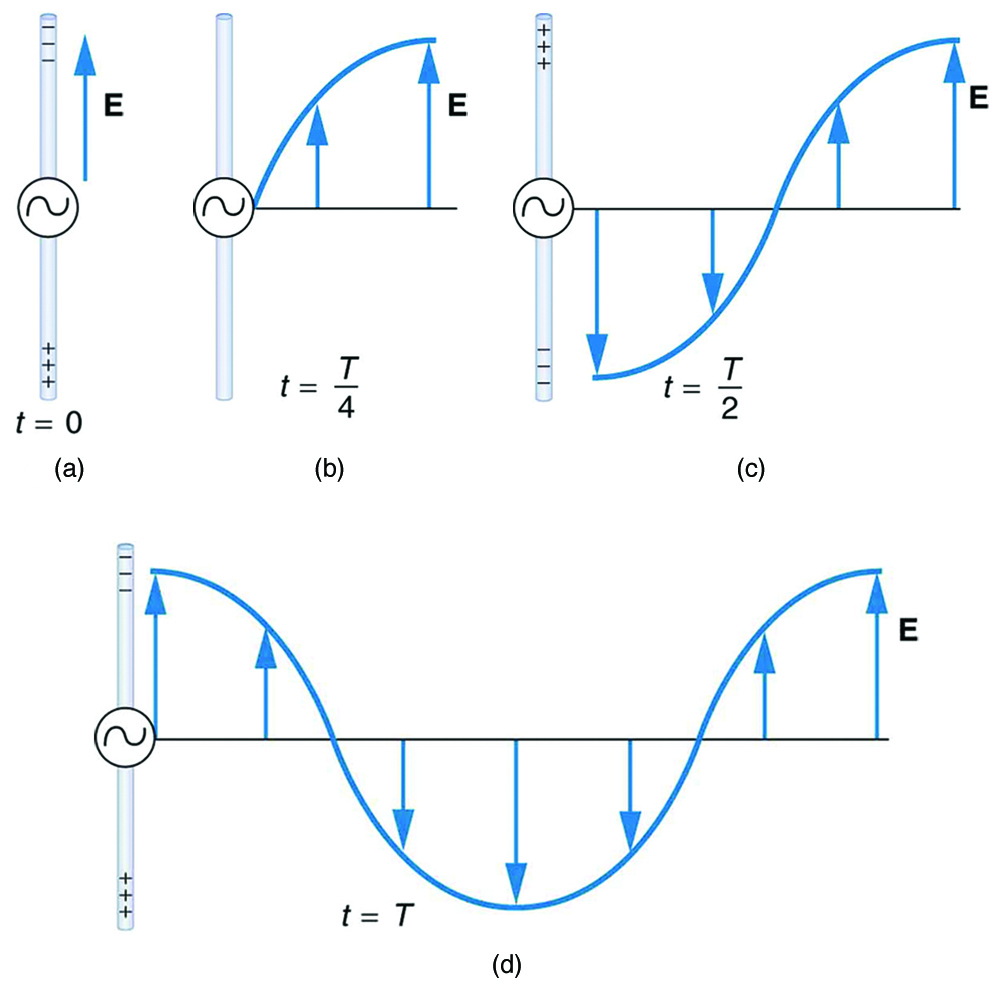
When an electrical signal travels along a transmission line, it behaves like an electromagnetic wave. This wave carries energy along the conductors and the surrounding electric and magnetic fields.
Important characteristics of transmission lines include:
- Voltage and current vary along the length of the line.
- Signals propagate with a finite velocity.
- Impedance mismatches can cause signal reflections.
Transmission line analysis becomes especially important when the wavelength of the signal is comparable to the length of the conductor.
Types of Transmission Lines
Transmission lines come in several different forms depending on their construction and application.
Two-Wire Transmission Lines


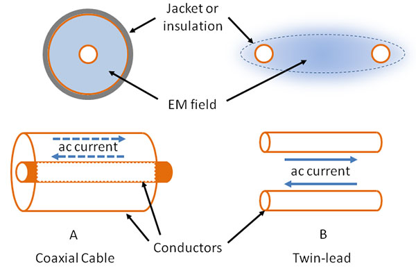

A two-wire transmission line consists of two parallel conductors separated by an insulating medium.
Characteristics include:
- Simple design
- Used in early radio systems
- Relatively low cost
Examples include:
- Open wire lines used in antenna systems
- Twin-lead cables used in television antennas
These lines guide signals through electric and magnetic fields formed between the conductors.
Coaxial Transmission Lines


A coaxial cable is one of the most commonly used transmission lines.
It consists of:
- A central conductor
- An insulating dielectric layer
- A cylindrical outer conductor
- A protective outer sheath
Advantages include:
- Excellent shielding against interference
- Low signal loss
- High-frequency capability
Coaxial cables are widely used in:
- Cable television systems
- Internet networks
- RF communication systems
Microstrip Transmission Lines


Microstrip lines are commonly used in microwave circuits and printed circuit boards.
They consist of:
- A conducting strip on a dielectric substrate
- A ground plane beneath the substrate
Microstrip transmission lines are widely used in:
- Microwave circuits
- Wireless communication devices
- Integrated circuits
They allow compact and efficient signal transmission in electronic devices.
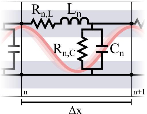
Transmission Line Parameters


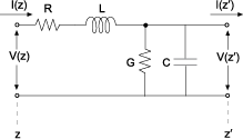
Transmission lines are characterized by four distributed electrical parameters.
Resistance (R)
Represents conductor resistance causing energy loss.
Inductance (L)
Represents magnetic energy stored in the line.
Capacitance (C)
Represents electric energy stored between conductors.
Conductance (G)
Represents leakage current through the dielectric.
These parameters determine the electrical behavior of the transmission line.
Transmission Line Equations


The behavior of voltage and current in transmission lines is described by the telegrapher’s equations.
[
\frac{\partial V}{\partial x} = – (R + j\omega L) I
]
[
\frac{\partial I}{\partial x} = – (G + j\omega C) V
]
These equations describe how electrical signals propagate along transmission lines.
Solutions to these equations show that signals travel as waves along the line.
Characteristic Impedance
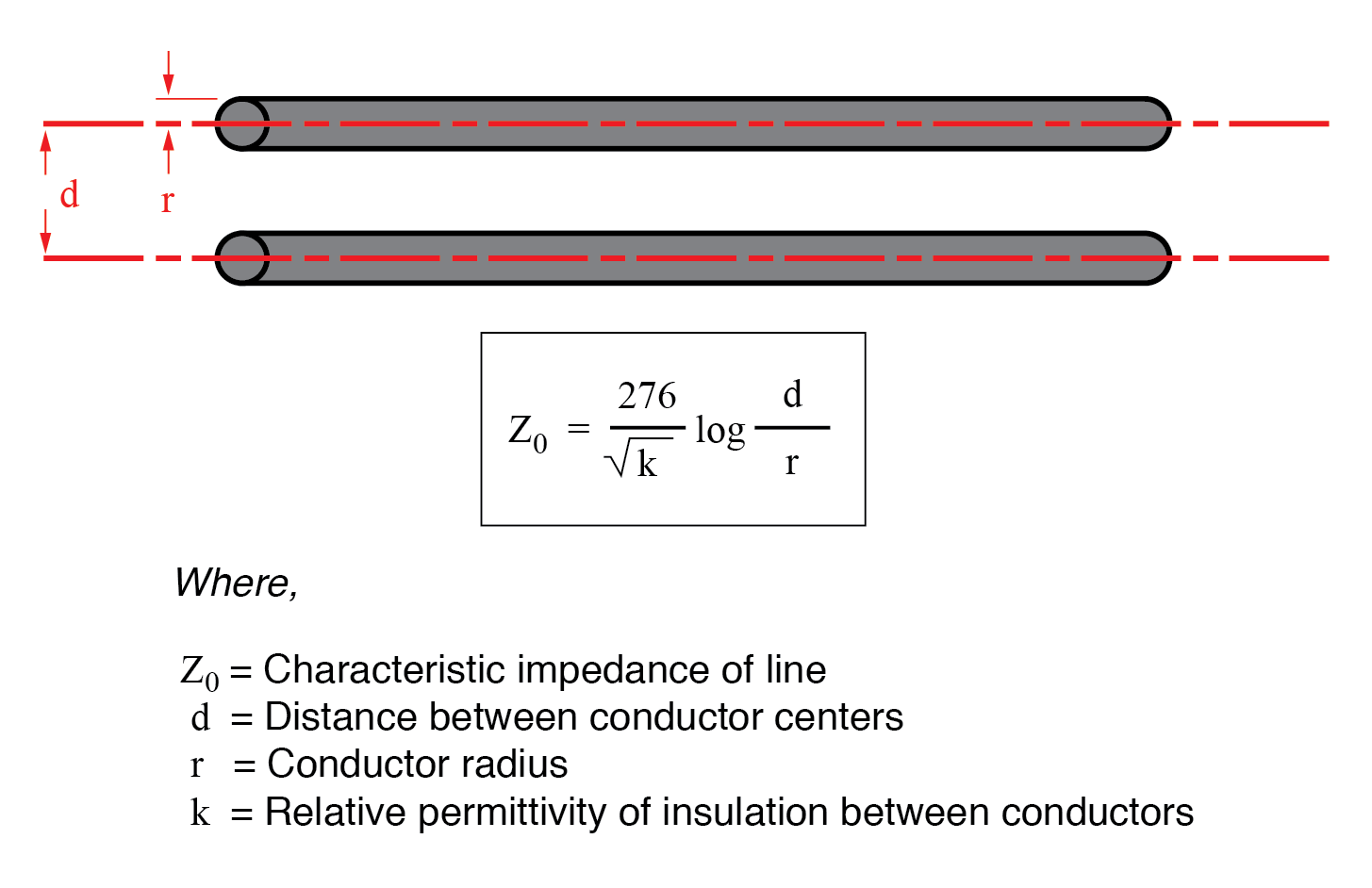
The characteristic impedance of a transmission line is an important property.
[
Z_0 = \sqrt{\frac{L}{C}}
]
Where:
- (L) = inductance per unit length
- (C) = capacitance per unit length
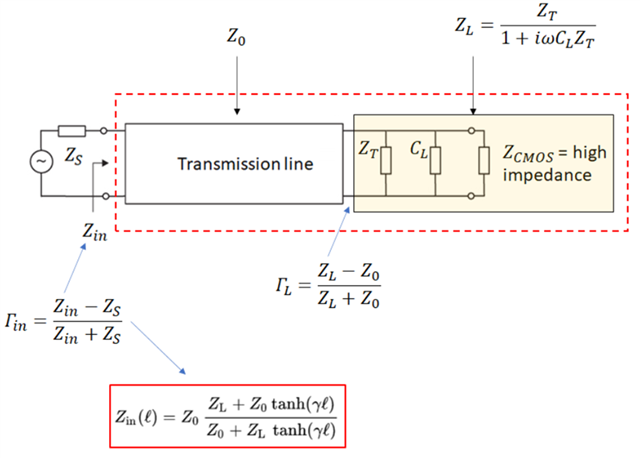
When the load impedance equals the characteristic impedance, signal reflections are minimized.
This condition is known as impedance matching.
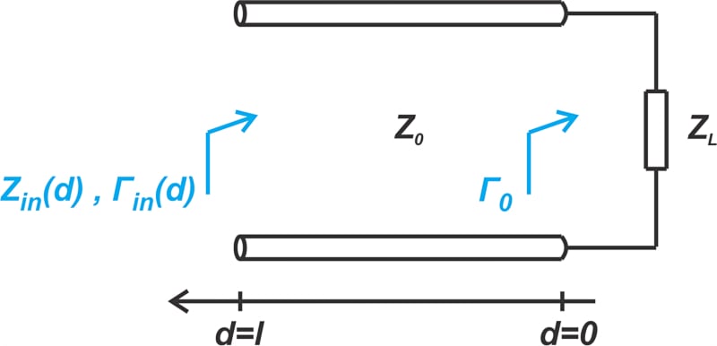
Signal Reflection and Standing Waves
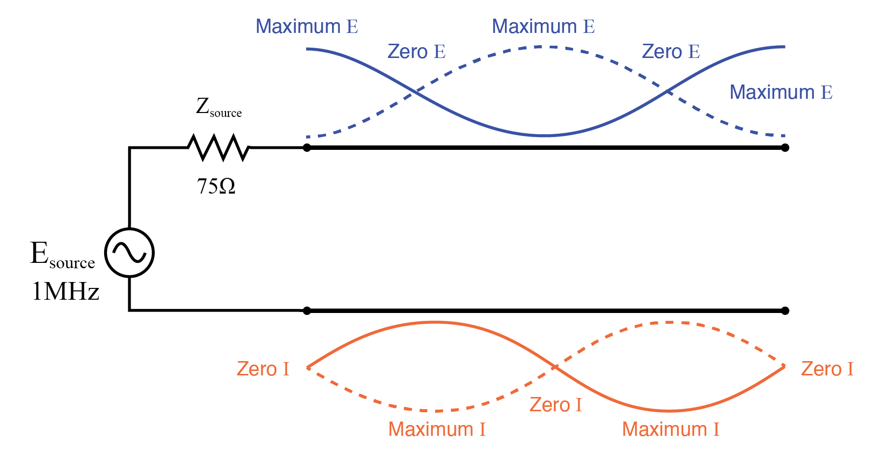


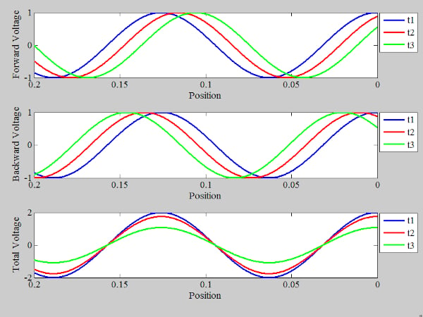
When a signal reaches the end of a transmission line, part of the signal may reflect back if the load impedance does not match the characteristic impedance.
This reflection creates standing waves along the line.
Standing waves produce variations in voltage and current along the transmission line.
The degree of reflection is measured using the Voltage Standing Wave Ratio (VSWR).
Applications of Transmission Lines


Transmission lines are essential in many technologies.
Electrical Power Systems
High-voltage transmission lines carry electrical power over long distances.
Telecommunications
Transmission lines carry signals in communication networks.
Radio Frequency Systems
RF transmission lines connect transmitters and antennas.
Computer Networks
Coaxial cables and other transmission lines carry digital signals.
Transmission line technology forms the backbone of modern communication infrastructure.
Importance in Electrical Engineering
Transmission lines are crucial for efficient signal transmission and power distribution.
They allow engineers to control signal propagation, reduce losses, and prevent signal distortion.
Understanding transmission line theory helps design efficient communication systems, radar systems, and electronic circuits.
Conclusion
Transmission lines are structures designed to carry electrical signals or electromagnetic energy from one point to another efficiently. They are essential in high-frequency electrical systems where signals behave as waves rather than simple currents.
Different types of transmission lines, such as two-wire lines, coaxial cables, and microstrip lines, are used in various applications. The behavior of transmission lines is governed by distributed electrical parameters and wave propagation equations.
Transmission lines play a fundamental role in modern electrical engineering, telecommunications, and power systems, making them an essential component of modern technology.